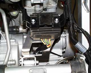
The original rubbers with spacers and sheet metal nuts are installed on the new mounting bracket as shown in the photo.
62
The original engine computer bracket is now installed on top of the voltage regulator using two new M6x60 bolts (5mm hex key), washers and the two aluminum spacers. The wires for the voltage regulator are placed through the mounting bracket and secured in place using a loop clamp. Be sure the wires cannot rub against any of the sharp edges on the mounting bracket.
63
This assembled unit is now attached to the frame using an M6x60 bolt with washers and a locknut. It will mount where the original shock reservoir mount was located, if necessary washers can be used to take up any space between the frame and the mount. After installing the unit and connecting the electrical connections the original wiring cover from step 54/55 can be reinstalled.
64
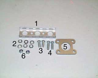
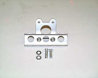
The parts for the shock reservoir mounting bracket.
(1)Sheet metal mount for the reservoir.
(2)Six M6 washers
(3)Two bolts M6x16 Button head
(4)Two bolts M6x20 Button head
(5)Bracket from frame to the sheet metal bracket
(6)Two M6 self-locking nylock nuts
65
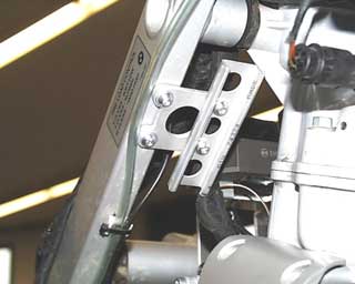
Pre-assemble the mounting bracket for the shock reservoir.
The two pieces of the bracket are bolted together using the M6x16 bolts with 4 washers and the two locknuts.
66
Mount the bracket to the frame using the remaining two M6x20 bolts and washers. On the two edges of the sheet metal bracket two pieces of rubber hose 100mm long can be split open and placed over the edges to protect the shock reservoir from being damaged.
67
The two hose clamps 40-60mm can now be placed through the slots in the mounting bracket and the shock reservoir clamped in place.
68
Install the front sprocket guard, either the original plastic cover or the optional aluminum cover. Do not forget to hook up the micro switch wire with the toothed washer from Step 60.
69
Remove the tail/brake lamp assembly from the original rear frame. The lamp is secured with four bolts (torx25) two from above and two from below. Remove the three nuts (10mm wrench) that hold the lamp to the plastic fender piece. Disconnect the wires and remove the tail lamp. Remove the torn signal lenses pull out the light socket and disconnect the wires. The turn signal wires can now be removed from the turn signal by pulling from the inside of the luggage compartment. The entire wiring harness for the tail/brake lamp and the turn signals can now be removed from the frame.
70
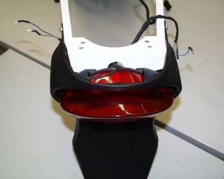
The three rubbers and spacers from the tail lamp should be installed into the new rear fender, and the tail/brake lamp can be installed. The wires are re-connected.
Brown (31)
Grey/Black (58)
Green/Red (54)
The new rear fender with the tail lamp is installed onto the frame using four M6x16 button head bolts with large washers.
71
The two threaded rubber spacers (30/20 M8) are attached to the rear frame using two M8x10 bolts.
72
Insert the rubber bushing and the metal sleeve into the aluminum exhaust hanger. The exhaust hanger is then secured to the frame using one M6x35 (1) button head bolt and one M6x30 (2) button head bolt. Both bolts get a washer and locknut.
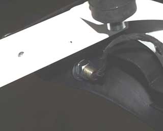
The fender must be drilled for the installation of the new turn signals. Drill the holes so the lights are straight and in alignment with the tail lamp, approx. 80mm from the top, and 35mm from the front edge of the fender. Drill the new holes to a 10mm diameter.
73
Install the turn signals and tighten the M10 nuts and washers from the inside of the fender. The original turn signal wires must now be routed through the new signal housings and connected to the new sockets. Make sure you have the correct right and left hand signals installed with the small drainage slots on the bottom.
74
Assembly of the center tank onto the rear triangle.
From the front place the tank into the frame. Place the two spacers into the tank.
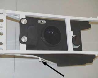
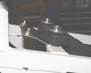
A tap should be used and all the threads in the new framework should be retapped since they may be covered in paint. The indicated thread in the photo must be cut all the way through since it will be used for the inner fender mounting bracket as well.
75
The upper mount for the inner fender is placed between the tank and the frame and secured along with the tank using two M8x40 socket head bolts. (6mm hex)
76
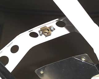
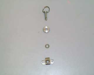
Install the quick release mechanism for the seat to the frame. The mechanism is secured using two M3x10 Phillips head screws with washers and locknuts.
77
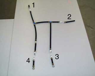
The fuel line connections will be as follows:
(1) The left front
(2) The right front
(3) The right rear
(4) Left rear
78
The right front fuel line runs under the shock reservoir hose and out.
79
The right rear line runs over the brake line and over the frame, forward of the connection for the rear frame triangle.
80
The left front "T" is situated beside the clutch lever and the left front hose runs under the clutch cable and out.