   |

 | 
81 | 
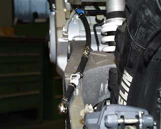
The left rear fuel line runs along the left side of the swing arm. |
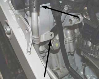 | 82 | Remove the mounting tabs of the oil lines at the motor. (torx25) Move the silver line out of the way and remount the black line to the motor. |
 | 83 | Place an oil pan under the motor and remove the oil line from the bottom of the motor (22mm wrench) When removing the oil line a small amount of oil will come out of the line. Remove the clamp from the hose that connect the line to the oil tank, and remove the oil line working it up from between the motor and the frame. Save the hollow banjo bolt from the oil line connection as it will be reused with the new stainless steel oil line.
NOTE: If an oil change is planned this is a good time to drain the remainder of the oil from the motor. |
 | 84 | Install the new rear triangle.
Install the new rear sport frame to the original mounting spots. The two lower mounts are installed using two M8x20 countersunk bolts (5mm hex), and the two upper using M8x20 socket head bolts. (6mm hex) All four bolts are tightened to 15ft/lbs.
TIP: A slight coating of grease can be applied to the frame where the tail contacts the frame tabs as well as under the heads of the countersunk bolts to protect the finish. |
 | 85 | Connect the fuel lines to the central tank.
The line is connected to the tank using a new banjo bolt and two washers, one on either side of the fitting. Carefully tighten the bolt. Once all the tanks are installed recheck the banjo bolt and all fittings for tightness. |
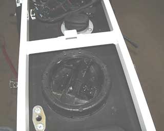 | 86 | The original fuel pump in now removed from the original tank. Loosen the large round nut that secures the pump into the tank. Lift upward to remove the pump. Be careful the pump can still be holding some gasoline. Take the seal from the tank and install it into the new tank, now lower the fuel pump into the new tank. Turn the pump in such a way that the fuel lines are toward the left. Make sure the electrical plugs will reach the pump and secure the pump using the original large round nut. |
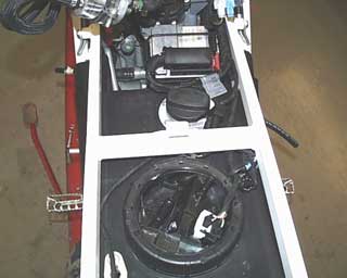 | 87 | The engine computer is connected and reinstalled with the original rubber band. The plugs of the fuel pump are also reconnected. The plugs are polarity safe and cannot be hooked up incorrectly. |
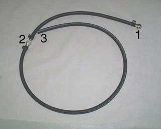 | 88 | The connections for the tank vent hoses are as follow:
(1) The rear tail tank
(2) The center tank
(3) The left front tank |
 | 89 | The fuel lines are reconnected to the fuel pump. The original band clamp is replaced with a screw type clamp. (8-12mm), the second line is connected with its original screw clamp. Make sure the fuel lines will not interfere with the seat mount, or rub against the seat tab when the seat is installed. The vent hose is now attached to the central tank using a banjo bolt and two sealing washers.(2) |
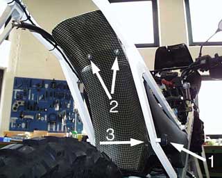 | 90 | Install the inner fender.
On both sides of the rear triangle install the rubber tank mounting bushings (1). These install using the M8x16 shallow head cap screws, with the label on the rubber bushings faces outward. On the right side the mounting plate for the inner fender is mounted using an M8x16 socket head bolt, it mounts on the inside of the threaded boss where the rubber tank bushing is mounted. The inner fender is secured with two bolts M6x20 button head (2) and large washers. The third bolt is M5x16 (3) and secured to the mounting plate, also with a large washer. |
 | 91 | Empty the brake fluid reservoir, remove the clamp and remove the hose from the reservoir. Shorten the hose approx 50mm and reconnect the hose to the reservoir and secure the clamp.
NOTE: Brake fluid is flammable and hazardous to your health. |
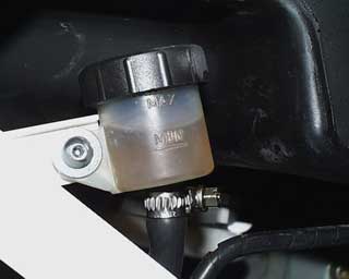 | 92 | Mount the brake fluid reservoir to the frame with an M5x12 button head bolt and large washer. Refill the reservoir according to the original manufacturer specifications.
NOTE: While working with the brake reservoir, DO NOT operate the brake pedal, if so you will need to bleed the rear brake of any air. |
 | 93 | Connect the new stainless steel oil line to the bottom of the motor using the original banjo bolt and two new sealing washers. When installing the line make sure the fitting on the other end for the oil cooler is pointed downward. Tighten the bolt to 25-30ft/lbs. |
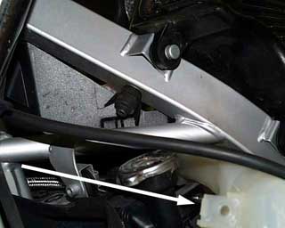 | 94 | Loosen the coolant tank (10mm wrench) and pull outward. |
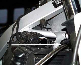 | 95 | Place the new oil line alongside the water hose, and above the radiator to the right side of the frame, between the frame and the radiator mount. |
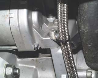 | 96 | The oil line is supported with the small bracket installed under the forward starter bolt. The line is secured to the bracket with a cable tie. Do not tighten the cable tie until the lines are completely hooked up and situated. |
 | 97 | Prepare the second oil line.
Insert the aluminum hose reducer fitting into the end of the hose. Remove any tape from the hose and install the 50mm piece of heat shrink tubing. Shrink the tubing to protect the end of the hose and install the hose clamp. |
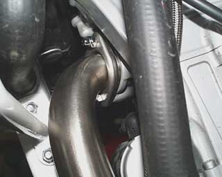 | 98 | Install the modified exhaust head pipe. Reuse the original domed nuts and the thin metallic gasket from the original pipe. The pipe runs down and through the foot peg mounts. Where the exhaust pipes slip together some copper anti-seize should be used to lubricate. |
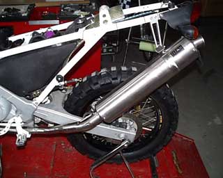 | 99 | The connecting pipe and the Titanium muffler should be put together and connected to the head pipe. The hooks for the connection springs should be in alignment. The exit of the muffler should be aimed out the back correctly. The clamp for the muffler can be installed with an M8x25 bolt and washer through the hanger. Once the entire exhaust is connected the two domed nuts at the cylinder head can be tightened to 15ft/lbs. Install the tension springs. |
 | 100 | Modification of the airbox cross member. The two round pegs that were used to secure the original seat need to be cut off. Once they are removed and the burrs ground smooth, the cross member can be repainted. |


